
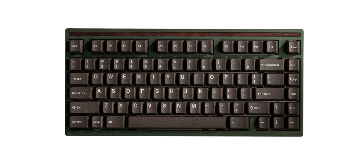
Envoy Build Guide
Build Time: 45-90 minutesThis guide will help you assemble your new Mode Envoy. The process should take about 45 minutes for hotswap builds and 1.5 hours for soldered builds. Prior to assembly, be sure to gather all the necessary parts and tools in your workspace. If you have any questions during assembly, please send us a message using the help widget below or chat with community members in the #build-support channel of our Discord server.
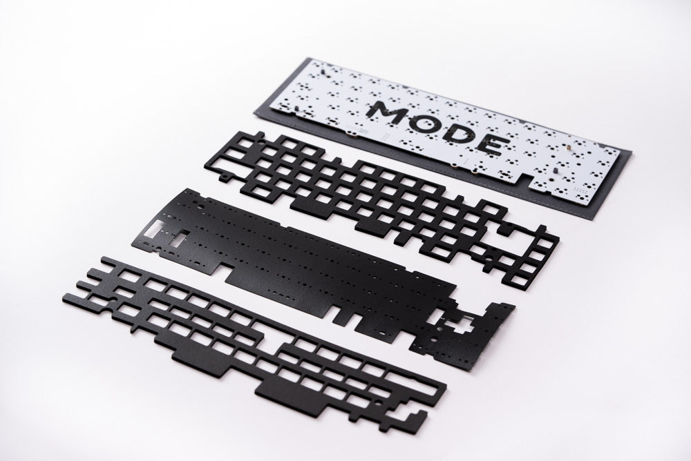
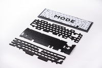
Parts
- Case
- Plate
- PCB
- Daughterboard
- Lattice Blocks x6
- Solid Blocks x6
- Feet
- Fastener Pack
- Keycap and Switch Puller
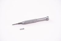
- Screwdriver + Bits
-
Foam Kit
Not Included
-
Switches
x70Not Included
-
Keycaps
Not Included
-
Stabilizers
Not Included
Preparation
Check that you have the required parts and tools listed above. We recommend the following steps to get the most out of your Encore.
Lubing Stabilizers: This reduces the rattling sounds that stock stabilizers produce. We have our own video tutorial available here.
Lubing Switches (optional): This dampens the sound of your switches and increases their smoothness. Lubing switches is a time-consuming process, but the results are noticeable. Taeha Types and Alexotos have video tutorials available for this as well.
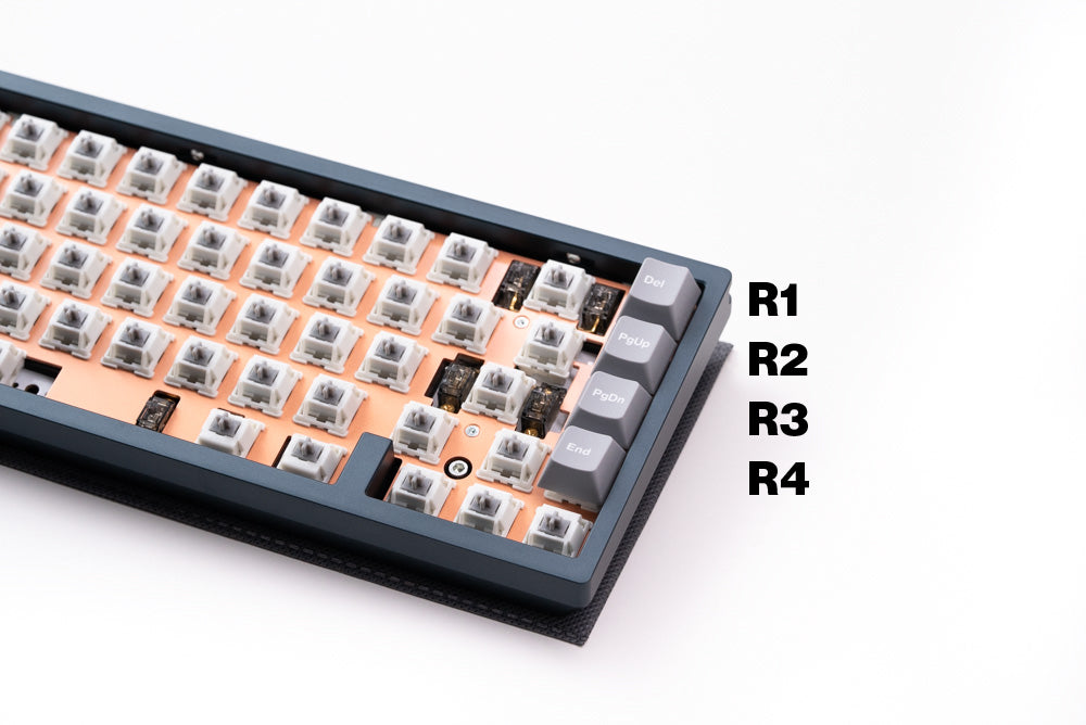
Mounting Styles
The Envoy has a newly designed internal mounting system to fine-tune your typing experience. Learn more about this mounting system here
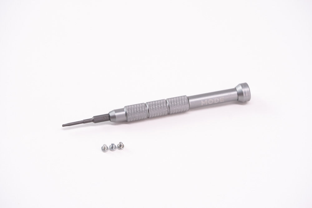
Fasteners

There are up to 4 types of fasteners used during this build. This diagram can be referenced to confirm that you are using the correct ones. Use the included H1.5 hex bit for M2 fasteners and H2.5 bit for M2.5/M3 fasteners.

Step 1: Test PCB


Do not skip this step; we cannot guarantee a replacement PCB that was not tested prior to assembly.
-
Place the PCB facedown, connect the daughterboard to the PCB, and plug it in. Be careful not to bend the connector pins.
-
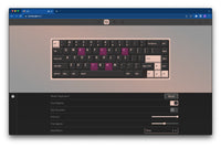
Open VIA, on the Configure tab click 'Authorize Device' and select the PCB. Navigate to the Key Tester Tab, and enable Test Matrix Mode.
-
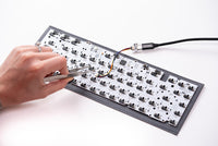
Touch the ends of your tweezers to the metal contacts under each switch position, lighting up each key in VIA. Note that the function key will not light up.
-
In the rare event that keys do not light up, pause your build here and contact support@modedesigns.com.
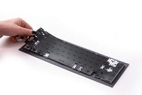
Step 2: Install Lower Feet


-
Align the two lower silicone feet into the recessed channel.
-
Press on the feet to ensure they are properly adhered.
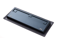
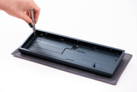
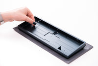
Step 3: Install Dot Feet and Weight

-
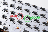
Align the dot feet onto the back of the Envoy weight (two total).
-
Press the weight into the recessed channel on the back of the chassis, ensuring the screw hole faces the bottom of the chassis.
While supporting the weight from the back, flip the board over and screw in the weight with the three M2.5x3 screws.
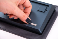
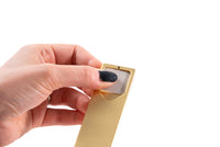
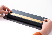
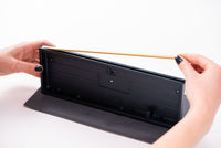
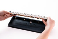
Step 4: Install Accent


-
Align the accent piece with the top of the chassis; orientation does not matter as long as the screw holes are facing towards the chassis.
If you choose to screw in the accent using the screwdriver, use caution to ensure you don't scratch your chassis. We recommend using just the screwdriver bit to screw in the accent.
-
Screw in the accent using the M2.5x3 screws (three total).
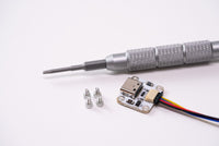
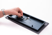
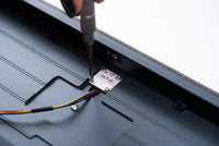
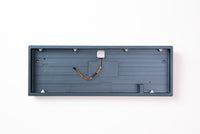
Step 5: Install Daughterboard


-
Connect the daughterboard cable to the daughterboard.
-
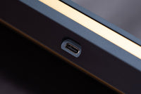
Fasten it into the bottom case using the M2x3 fasteners (four total) with the USB-C port facing downwards.
Take care to not overtighten the fasteners, or you may damage the daughterboard.
Step 6: Insert PE Foam

-
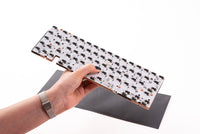
- If you plan to use the optional PE foam, lay it on top of the PCB now (foam kit sold separately).
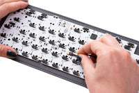
Step 7: Install Stabilizers

Stabilizers ensure that long keys actuate properly, no matter where you press. The stabilizer wire you need for the spacebar will depend on your choice of layout.
-
- Insert the non-threaded end of the stabilizer into the larger cutout on the PCB, then pivot the threaded ends into place.
-
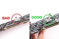
- Ensure that your stabilizers are completely flat on the PCB before screwing them in.
-
- While bracing the front of each stabilizer, screw it into place from the underside of the PCB. Repeat for the remaining stabilizers.
Step 8: Prepare to Install Switches


-
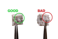
- Before installing your switches, inspect them to ensure the two metal pins on the underside of each switch are straight. Straighten all pins with tweezers if any are bent.
-
- If you plan to use the optional plate foam for a more dampened sound, lay it on top of the PCB now.
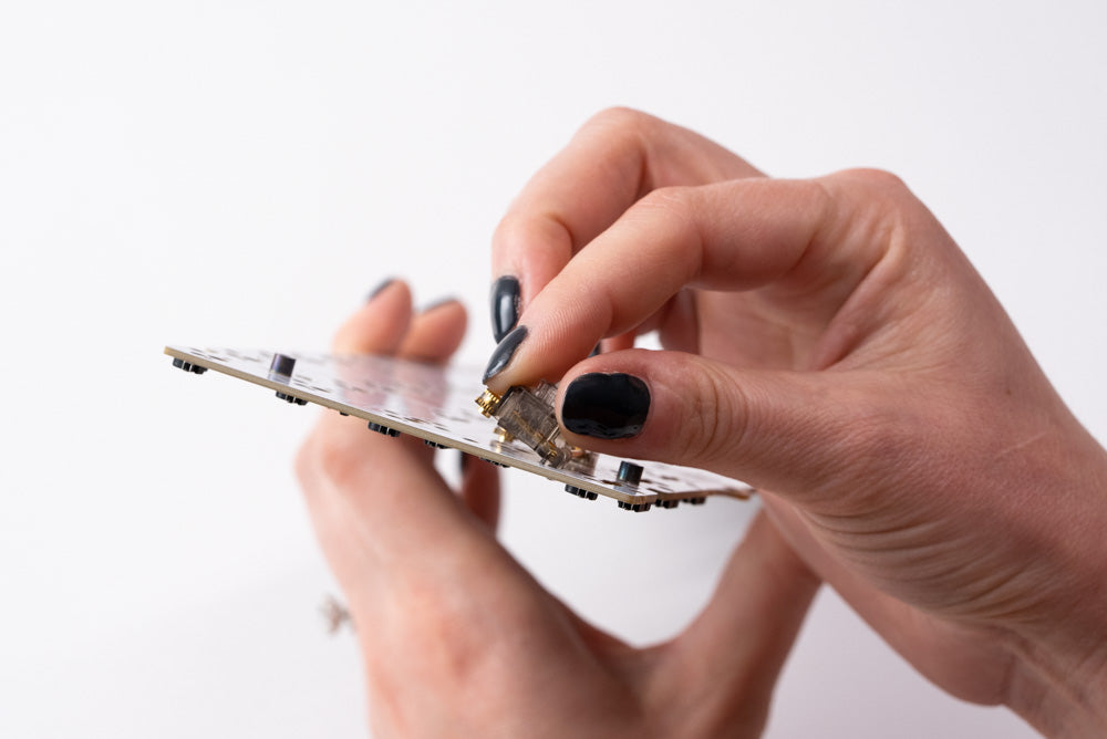
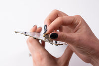
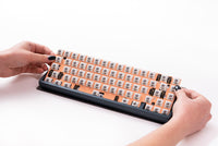
Step 9: Install Switches


-
- Remove the orange covers on top of the standoffs, align the plate with the PCB, and fasten it into place with the four M2x3 flat head fasteners.
-
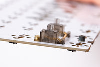
- Insert switches into the plate/PCB. Brace the back of the hotswap socket with a finger while pushing the switches into place. Do not apply downward pressure to the plate itself.
If you're using a soft plate material such as POM, ensure switches are fully seated. We recommend using the screwdriver to carefully lift the plate while pressing down on the switch to ensure the switch is seated in the plate.
-
- If you are using a solder PCB. Solder your switches now.
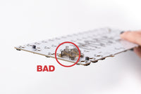
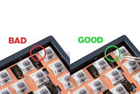
Step 10: Confirm Switch Installation


Switches that are not properly installed can cause alignment issues when the case is closed.
-
- Check that the plate is not sagging below the tops of the switches.
-
- Check that each switch pin is fully seated into the PCB.
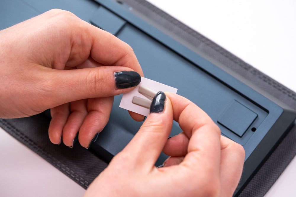
Step 11: Install Mounting Blocks


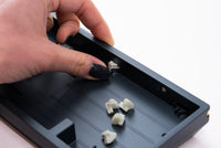
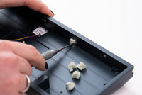
-
- Slide your preferred mounting block into the recesses within the chassis (6 total).
-
- You can mix and match or swap these blocks to fine tune your typing experience.
To ensure a proper fit, you can carefully use the tip of the screwdriver to push the stem of the mounting blocks into place.
Step 12: Attach Plate/PCB to Chassis


-
While holding your plate/PCB assembly, use your other hand to attach the daughterboard cable to the PCB
Check the orientation of the daughterboard cable and ensure that it is fully plugged in. It should not come loose if inserted properly.
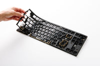
-
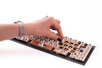
- Gently lower the plate/PCB assembly into the chassis starting with the bottom of the plate/PCB.
-
- Secure the plate/PCB assembly to the chassis via the M3x9 fasteners with the 2x Rubber Washers.
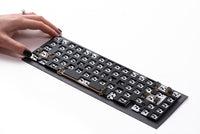
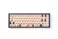
Step 13: Install Keycaps


-
Install your choice of MX-compatible keycaps.
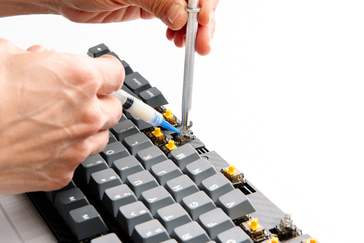
Step 14: Tune Stabilizers


-
- Test the stabilized keys for any undesired rattling noises.
-
- If rattle is detected, lift the corresponding stem up and inject lube into the slider around the ends of the stabilizer wires.
Step 15: Set macOS layout


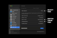
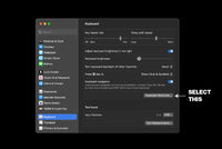
If you are using your Envoy with a Mac, switch the Command and Option key positions in System Preferences. You will only need to do this one time, and the positions will be correct for both Mac and PC usage.
Step 16: Program Keymap in VIA/QMK
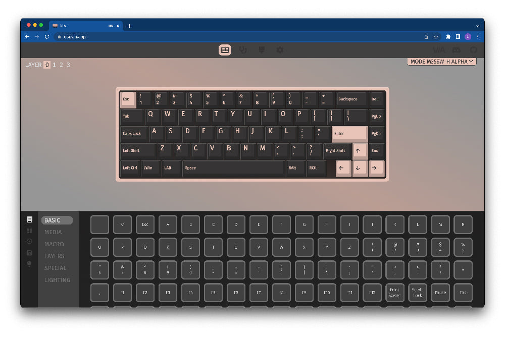


- The Envoy is fully compatible with VIA and QMK. You can use the graphical interface of VIA to program any of the keys or layers on the Envoy.
-
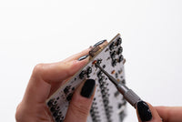
- If using QMK, you may enter bootloader mode by pressing the physical reset button on the board or pressing Fn + Esc.
-
- If any of the keys do not actuate properly, it may be due to a bent switch pin during installation. Remove that keycap and switch using a keycap/switch puller. If any metal pins are bent, straighten them with a pair of tweezers.
Happy Typing
We hope you had a smooth build experience and would love to see the end result! Post your build in our photos channels on Discord or tag us on Instagram @modekeyboards. If you have any feedback you'd like to share with us, you can reach out to hi@modedesigns.com.